◊ Historic Buchla Modules

Buchla pages > Buchla 100 modules > 111 Dual Ring Modulator


Model 111 Dual Ring Modulator

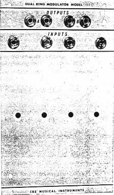
Two independent ring modulators. Each output consists of the sums and differences between frequency components of two input signals. Original signals are suppressed about 55 dB.


DIY Resources

  • Schematics:
  • Errata:
    • On the CBS schematic, R38 and R89 (47Ω) should be tied from Q8/Q28 to V+ (instead of back to a couple of other transistors). The schematic on LA67's site shows this correctly. This is correct on the PCB.
    • The output caps (C4, C5, C21, C22) are shown as 56uf on the CBS schematic, they should be 5.6uf (tantalum in the original). PCB shows correct values.
    • Based on examination of an actual unit, Apetechnology reports that R27 and R78 (given as 680Ω on the CBS schematic) should instead be 680k
  • Builds: David Brown's essential build/repair notes, including mods and trimming instructions.
  • PCBs: I offer Printed circuit boards for this module (2 PCBs required for a dual unit); FPD files also available for making panels.