
Last week we built our first oscillators, based on the 40106 chip. Hopefully you were able to get several oscillators working, mixed some of the outputs together, and maybe even connected 2 oscillators together (using the diode) so that one oscillator controls (or “modulates”) the other. That basic building block allows hundreds of variants — stringing them together in different ways, mixing, and various ways of controlling--so don’t shortchange the possibilities of just that one chip, and keep playing.
This week we’ll introduce a very similar oscillator using a different chip, which will allow you to connect them together in a slightly different way. (BTW, this again is straight out of the Nic Collins book, which I will recommend again.) The new chip is the 4093 quad NAND gate, and here’s its pin-out:
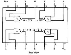
First, notice the circuit elements: 4 identical NAND gates, which implement a particular logic rule… which you could look up if you care. Each of those bullet-shaped things is a gate, with 2 inputs (pin 1 and 2 for the first gate, for instance) and one output (pin 3 for the first one). Both inputs of a gate are the same (you can use whichever one is handiest for your layout), and each gate is identical. Last thing to check is the power: like the 40106, VDO (pin 14) is the positive power connection, VSS (pin 7) is the negative or ground. (Note: THIS IS NOT ALWAYS THE SAME FOR EVERY IC: BE SURE TO CHECK THE DATA SHEET).
So that’s the IC, here’s the schematic for our basic oscillator, using 1 inverter, 1 resistor, & 1 capacitor:
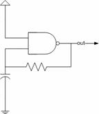
This should look very familiar; it’s just like the 40106 oscillator, except that the inverter had one input and the gate has two. We’ll have to supply a logic signal (high or low) to the new second input of the gate to control the oscillation. If that signal is low (0v), the oscillator won’t go; if it’s high (9v) it will--that’s the trick we’ll use when we start connecting oscillators together.
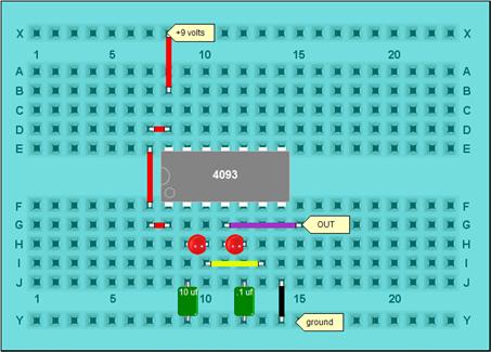
The schematic doesn’t tell you which specific IC pins to use, but you can figure it out by referring to the pinout diagram. I usually pencil in the pin numbers on my schemo before I start, to cut down on the confusion. When I built it, I decided to use the first gate (1 & 2 for input, 3 for out). So go ahead and wire it up like last time, starting with the power connections, then the cap and resistor.
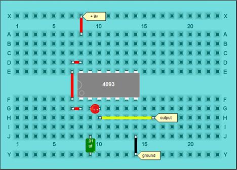
The red thing between pins 2 & 3 is the resistor, standing on end; start w/ 100k, or variable (pot, photocell). This also shows 3 jumpers to pick up the power from pin #14 and apply it to pin #1--you can run just one wire, or use the double buss lines on the edges of the breadboard so you can have power and ground on both sides of the chip.
Power it up, make sure nothing smokes, and connect to your amp; it should sound pretty much like the 40106 oscillator. So what. Next step is to add a second oscillator using the second gate and connect them together. Here’s your schemo:
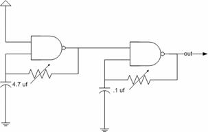
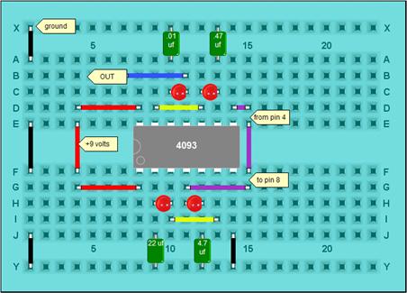
One oscillator after the other. I used the next gate on the same side of the chip, pins 4, 5 & 6. The schemo shows a large value cap for the first oscillator, so it will be slower. Anything between 1 and about 25uf will do; so swap in an electrolytic cap, making sure to watch the polarity (negative to ground). Anyway, here’s (one possible) layout:
The yellow jumper is the connection between oscillator 1 and 2. You should hear oscillator 2 beeping on and off, the rate of beeping being determined by oscillator 1.
Here’s what’s going on: remember how we had to tie one gate of the first oscillator “high” (to 9v) for the circuit to go? By connecting the output of the first oscillator to one side of the second gate, it turns the second oscillator on and off, or “gates” it. Beep beep beep.
Try different combos of caps… a couple of big caps can lead to some interesting rhythmic patterns; small caps can get more into screeching weasel territory. Either way, having some kind of variable resistors is key to keeping things interesting and making it playable.
So we got 4 gates on this chip, let’s use ‘em:
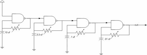
One oscillator controlling another controlling another…. that’s gotta be good, right? Like last week, it’s easiest if you build one oscillator at a time, make sure it’s working, and then adding it to the chain. With the cap values shown, the oscillators get progressively faster, which might be what you want or it might not. Build it up and see.
Something like this, perhaps:
There’s a bunch of things you could try at this point:
|
Credits & References:
|