This is a glitchy, lo-fi distortion effect for analog video signals. It was originally designed by James Schidlowsky via postings to Electro-Music.com; and was recently revived by Javier Plano (@Videonic) who designed and published a PCB design which you can freely download. I led a few workshops (see workshop documentation) using this design.
Fluxmonkey PCBs
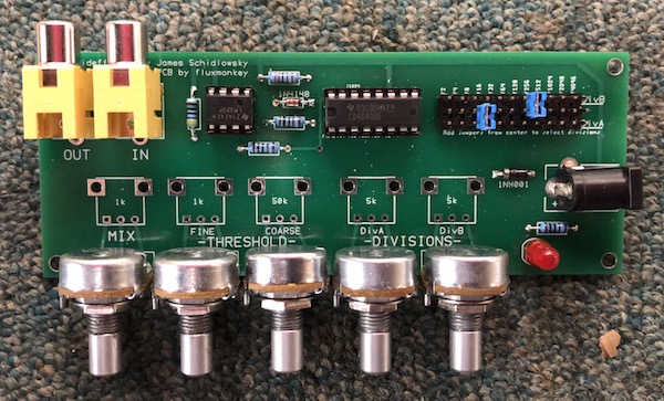
Based on feedback from folks in those workshops, I did a revised PCB design, with some changes/enhancements (this might make more sense after reading "how it works" below)
Exposed all of the available divisions via a header so you can select different ones (original was hardwired to /4 and /128)
Substituted a LM393 dual comparator for the 339 quad (only one is used)
Added footprints for for threaded-mount 16mm pots, in addition to the 9mm standalones.
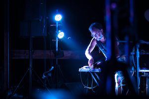
Connecting a video signal to the input and monitor to the out add various levels of distortion and artifacts, particularly to the edges of images. The effect is highly sensitive to both the video source and displays, and tends to have some "sweet spots" based on the control settings, with lots of noisey/staticky regions in between.
Example 1
Example 2
BOM
Here's the Bill of Materials for the revised board – I give part numbers from Mouser and Small-Bear, but you might fined them cheaper elsewhere:
You'll also need a 12VDC wall-wart power supply, 2.1mm positive center. You probably have one, but smallbear 2401I or similar.
Build Steps
All of the parts of the Videffektor mount directly on the PCB, making assembly super easy – place components in the holes following the legend, turn the board over, solder, and clip the leads.
If you have not soldered before, this will be an easy intro... call me over and we'll have you squared away in no time.
Inserting the parts in the following order puts the lowest-profile components in first, which helps keep them in place when soldering:
Start with the resistors – small blue cylindrical jobs with colored bands to show the values. Pinch the body of the resistor in one hand, and fold both legs down at the same time, not too tight to the body. Then follow the PCB legend and push the leads through the holes. Do them in this order:
2.2kΩ there's just one of these, color code red-red-black-brown-brown
470Ω – again just one, yellow-violet-black-black-brown
1kΩ – the remaining 3 resistors, brown-black-black-brown-brown
Turn the board over and lie it flat on the table so all the resistors are pushed flat against the PCB. Solder. Turn the board over to make sure everything stayed flat, and if all's good then snip the leads.
Diodes – there are two: the tiny glass one is the 1n4148, and the larger black epoxy one is the 1n4001. These are both poloraized (need to go right way around) – make sure the striped end of the diode matches the black stripe marking on the PCB legend. Insert, flip over, solder, and clip the leads.
IC sockets – there are 2, one with 8 legs and one with 16. There's a little divot on the ends, make sure they match the divot on the PCB legend. Turn over, solder one corner of each one, and then make sure they're laying flat; then solder the opposite corner and check again. It's a pain to unsolder a socket, so check twice, then go ahead and solder all the other pins.
Power connector – This is the large black one towards the back. The holes are round but the component tabs are flat – you don't necessarily need to fill the entire hole, but make sure there's a solid mechanical connection since you plug/unplug the power over time.
LED – or Light Emitting Diode, the shiny domed item. Like the other diodes, this is polarized... the slightly flattend side on the bottom of the plastic case should line up with the flattened side of the legend. These can go flush against the board, or a little (1/16") elevated.
Division Select header – All of the outputs from the CD4040 (binary division from /2 to /4096) are brought out to the center row of the 3-row header. There are a couple of options to build this:
Solder in the full header, and then use the removable shorting bars to select 2 divisors. This allows you to experiment with different selections, even when the unit is powered up.
Omit the header, and just add 2 jumper wires from different divisors in the center, one to each side. You can finish the rest of the build and then experiment with different placements, just jamming wires into the holes, and solder once you're happy with your selection
You could wire a pair of rotary switches, with the various divisor outs to different switch positions and the selectable poles of each switch go back to the DivA and DivB returns. Frankly, I find this to be over the top, considering the cost of rotary switches...
RCA jacks – Two yellow connectors, they should snap into their holes with a little click. Again, make sure the solder joints are mechanically sound, but no need to go overboard.
Pots – (short for "potentiometer"), the controls go in last. There are 5 pots with 3 different values, check the markings on the bottom and be sure to get them in the right places (B102=1k; B502=5k; B503=50k). Again, a couple of pot options, choose one:
9mm PC Mount pots with plastic shaft (part #1012A4) are good if you're leaving the PCB open. They click right into the square footprint, and have a couple of mechanical connections as well as the 3 smaller electrical connections. Go slow when soldering and flip the boards over to make sure everything's perpendicular as you go.
The 16mm Alpha pots (part #1010A) fit into the sets of 3 holes close to the edge of the board. These might work better if you're incorporating the Videffektor into something else, or building into a metal enclosure. The pot bushings can then secure the board to the box. I solder one leg of all five pots, and then check to make sure all are lined up evenly before soldering the other two legs.
And that's it. Check your work, make sure there aren't any globs of solder or leads folded over and shorting something out.
How it works
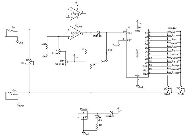
Here's a redrawn version of the Videffektor schematic:
It's routed to the LM393 Comparator, which compares the signal to a reference voltage – if it's higher than the reference, the output goes high; otherwise it stays low.
The two pots labeled Threashold/Course&Fine set the reference voltage for the comparator.
The output of the Comparator goes to a Divider, which takes the series of pulses and divides them into binary numbers: every 2 cycles output Q1 goes high, every 4 cycles Q2, every 8 cycles Q3, and so on. It essentially divides the frequency coming from the comparator by multiple powers of two.
All twelve divisions (/2 to /4096) are brought out to the middle row of the 3-row header. You need to select two divisions, using the jumpers, and connect them to the "DivA" and "DivB" selectors.
The DivA and DivB signals go to two Division pots, which independently control how much of those 2 signals are sent back to the Output, lower left.
The Mix pot mixes some amount of the original input signal back into the output. Turned all the way up, it sends the entire unaffected signal back out, effectively bypassing the effect.
When it's cranked up full, the effect basically destroys the Synch part of the analog video signal, and overwhelms the display's ability to decode it, resulting in hash. Different displays are better or worse at dealing with corrupted synch signals, which is why the results are so dependant on the video source and monitors you use.
Using the Videffektor
Coming soon: our own demos on how to use the Videffektor: process pre-recorded video, live feeds, feedback...
Resistors have values in ohms (with k meaning kilo- or thousands-of-ohms; m meaning meg or millions), and they’re labeled with colored bands that tell you their value. Here’s how it works:
Our resistors had a tolerance of ±1%, so they had 5 bands. So, "red-red-black-brown-brown" translates to 2 2 0 x10Ω (2,220Ω, or 2.2kΩ) at ±1% tolerence. You can always look it up on the interwebs, and there are aps. Being able to read color codes will be important if you start building stuff from scratch.