◊ PCB Documentation


111 Ring Modulator

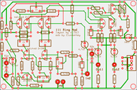
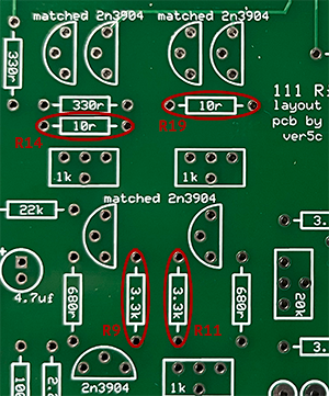
All-discrete ring mod based on the one half of the Buchla 111 circuit. Note: original 111 was a dual; this PCB is for a single ring modulator, so you would need two for a clone project. Adapted from PCB design by vtl5c3.

PCBs are $15.00 @ — ORDER HERE

Bill of Materials (value/qty)

  • Resistors
    • 10k x4
    • 100k x2
    • 1k5 x4
    • 220r x2
    • 2k2 x1
    • 22k x1
    • 330r x2
    • 3k3 x5
    • 33k x1
    • 47r x3
    • 680r x6
    • 6k8 x4
    • RA 22k x2 (optional input attenuators)
    • RB 1k x2 (optional input attenuators)
  • Capacitors
    • 2n2 x2
    • 0.1uf x1
    • 4.7uf x2
    • 5.6uf x2 *
    • 10uf x1
  • Transistors
    • 2n3904 x7
    • 2n3906 x3
  • Misc.
    • .100" 4-pin power header x1
    • ferrite bead x1 (or substitute 2.2r 1/2 watt resistor)

*Errata/Notes

[updated 02/23/2025]

  • On the schematic, R38 (47Ω) is shown tied from Q8 to several of the other transistors; it should instead be tied from Q8 to V+. This correction is made on our PCB.
  • The polarized 5.6uf caps by the outputs are shown as 56uf on the schematic; 5.6uf is believed to be correct.
  • R14 and R19 on our PCB are incorrectly marked as 10r; they should both be instead be 10k. Thanks to Dave Brown for pointing out this error. (see image below)
  • Dave also recommends the following resistor value changes to improve levels:
    • R14 and R19 from 10k to 1.5k
    • R9 and R11 from 3.3k to 1.5k

Notice

    The text, images, graphics, and other content of this website related to Don Buchla's legacy synthesizer designs is made available under the Fair Use Doctrine of the US Copyright Office. Fair Use limits the use of this information to personal, educational, and scholarly purposes (including right-to-repair, where applicable). It may not be used as the basis of commercial or for-profit works. Our Printed Circuit Boards may be purchased and assembled for your personal or educational use, but may not be manufactured and sold as "Buchla" products.