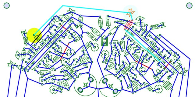
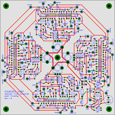
The Fourses Tarp is one of three variations on the Fourses noizy synths, designed by Peter Blasser of Ciat-Lonbarde (the other two are the Fourses Arpserge, and Fourses Tarpterge). All three versions were originally released as paper circuits - builders would print the layout on paper, glue to a piece of cardboard, punch holes for component leads, and then weave and solder the leads of the components together to simulate a printed circuit. This PCB is a translation of that design to an actual printed circuit board, for ease and reliability (at some expense to DIY self-sufficiency). You'll still want to grab Peter's original paper circuit PDF , which includes most of the build documentation you'll need.
Thanks to Peter for his design, and for giving his permission to provide these PCBs.
The Fourses series are "all based on the idea of four oscillators that bounce off of each other, creating animalistic noises". So there's a ring of signal generators, each modifying the other, which under the right conditions approximates chaos. There is a single pot control for each of the oscillator circuits, as well as 40 touch nodes – in practice these internal connections are exposed as touch points. Touching multiple nodes with your fingers (or connecting them with alligator clips / copper scrubbies / chains etc.) makes interconnexions between parts of the circuits, triggering and modifying the sounds, and adding to the chaotic behaviours. The result is a tactile and intuitive playing surface, with built-in indeterminacy. Also, fun.
This PCB also includes a simple onboard amplifier, based on the LM386 chip. To use this as a solo instrument, you'll want to connect the input of the amplifier to one or more of the touch nodes (or to a conductive object you can lay one or more nodes), and then take the output of the amp to listen or further modify. If you have other touch instruments, you can also interconnect the signlals from the touch nodes between devices – just make sure they have a common ground connection between them.
| Fourses Tarp BOM | |||
|---|---|---|---|
| QTY | Part | Description | Part Number * |
| 1 | 10r Resistor | 1/8 watt | 270-10-RC |
| 12 | 4.7k Resistor | 1/8 watt | 270-4.7K-RC |
| 16 | 10k Resistor | 1/8 watt | 270-10K-RC |
| 2 | 22k Resistor | 1/8 watt | 270-22k-RC |
| 28 | 100k Resistor | 1/8 watt | 270-100K-RC |
| 16 | 470k Resistor | 1/8 watt | 270-470K-RC |
| 12 | 2.2meg Resistor | 1/8 watt | 270-2.2m-RC |
| 4 | 50k Potentiometer | linear | 1012A-B50K or 1012A3-B50K* |
| 1 | 1N4001 Diode | black epoxy, observe polarity band | 863-1N4001G |
| 4 | .001 uf Capacitor** | MLCC | 581-SR211C102K |
| 4 | .01 uf Capacitor | MLCC | 581-SR211C103K |
| 4 | 1 uf Capacitor | MLCC | 581-SR211C105K |
| 2 | 10 uf Capacitor | electrolytic | 647-UVZ1J100MDD |
| 1 | 220 uf Capacitor | electrolytic | 667-ECA-1HM221 |
| 12 | BC549 | NPN transitor | 512-BC549BTA |
| 8 | BC559 | PNP transitor | 512-BC559BTA |
| 4 | IC LM358 | dual op-amp | 595-LM358P |
| 4 | CD4066B | quad analog switch | 595-CD4066BE |
| 1 | IC LM386 | amplifier | 926-LM386N |
| 5 | 8 pin DIL socket | for ic | 649-DILB8P |
| 4 | 14 pin DIL socket | for ic | 649-DILB14P |
| 4 | LED | observe polarity; flat side/short leg = cathode | 859-LTL-4223 |
* Mouser.com part numbers, except pots from Smallbear-electronics
** different values here change the frequencies, good place to start with mods.